The RC Circuit
Understanding how to correctly define the equivalent circuits of electrically excitable cells was the key to developing an understanding of the electrical function of cells, because the behavior of electrical circuits is very well understood.
The simplest equivalent circuit for an electrically compact cell is a resistor and capacitor wired in parallel (Figure 1). The pooled conductance of the cell membrane is represented by the resistor (Rm) and the capacitance of the entire membrane is represented by a single capacitor (Cm). This circuit is known as a parallel RC circuit, for obvious reasons.
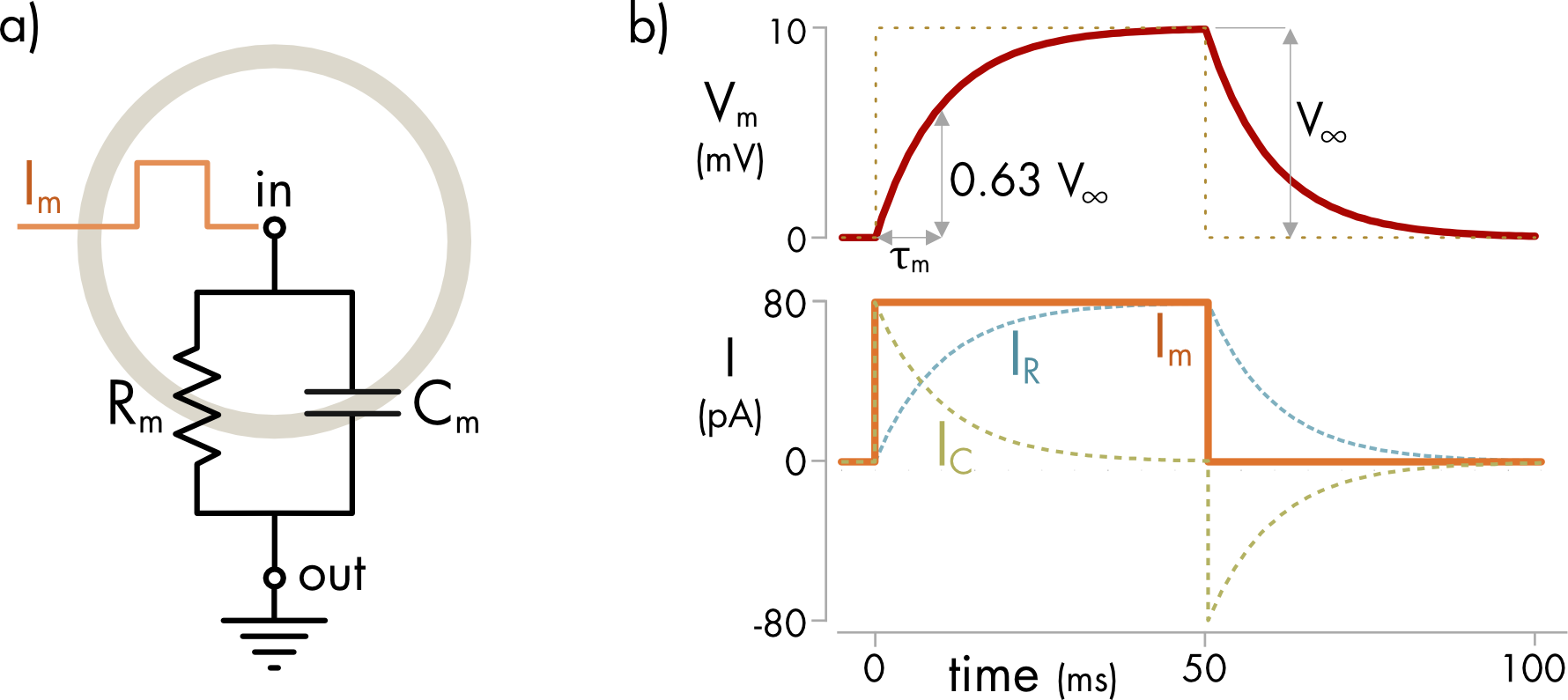
Figure 1 a) Equivalent circuit of a cell - the RC circuit. The total membrane conductance and capacitance are each represented as a single component wired in parallel. Current (Im) is injected at the node inside the cell and flows across the cell membrane to ground in the surrounding media. b) The voltage response (Vm) to a square pulse of current (Im) injected into an RC circuit with Rm = 127 MΩ and Cm = 78 pF. The expected voltage response if there was only a resistor in the circuit is shown as a dashed line. The presence of a capacitor slows the voltage response. The 80 pA injected current step (Im) is shown in orange. The current splits into two parts as it flows through the circuit. IC flows into the capacitor (green dashed line) and IR flows through the resistor (blue dashed line).
When current is injected into an RC circuit it flows either through the resistor or into the capacitor. Current flow into the capacitance is proportional to the rate of change of the membrane voltage. At first the rate of change is fast and essentially all the injected current flows into the capacitor. As charge flows into the capacitor the voltage across the circuit increases in proportion to the amount of charge transferred to the capacitor.
\[V_{m} = \frac{q}{C_{m}}\]
The increase in Vm results in an increasing fraction of the current flowing through the resistor as expected from Ohm’s law, and the rate of change of the voltage declines. If the current is sustained, the rate of change of the voltage falls to zero and at long times after the onset of the current step there is no capacitive current only a resistive current. Current flow through the resistor directly parallels the changes in voltage.
At the offset of the current step there is charge stored on the capacitor. This charge flows through the resistor to ground. As a consequence, the voltage declines slowly until all the charge has left the capacitor (Figure 1).
From Kirchhoff’s current law,
\[I_{m} = I_{R} + I_{C}\]
Current flow through the membrane resistance is given by Ohm’s law,
\[I_{R} = V_{m}/R_{m}\]
Current flow onto the membrane capacitance is given by,
\[I_{C} = C_{m}\frac{dV_{m}}{\text{dt}}\]
Combining and rearranging gives a differential equation for the dynamic change in voltage in response to current injection,
\[\tau_{m}\frac{dV_{m}(t)}{\text{dt}} = {- V}_{m}(t) + \ R_{m}I_{m}(t)\]
where \(\tau_{m} = R_{m}C_{m}\) is the time constant of the RC circuit.
For the circuit shown in Figure 1 the time constant is,
\[\begin{aligned}\tau_{m} &= 127 \cdot 10^{6}\ \Omega\ \times \ 78 \cdot 10^{- 12}\text{\ F}\\\\[-2ex] &= 10\ \text{ms}\end{aligned}\]
The time constant determines the rate of change of the voltage. If a current step is injected at time t = 0, the change in voltage is given by,
\[V_{m}\left( t \right) = V_{\infty}\left( 1 - e^{- t\text{/}\tau_{m}} \right)\]
where V∞ is the voltage at infinite time after the voltage step.
At the offset of the current step the change in voltage is described by a simple exponential decay,
\[V_{m}(t) = V_{\infty}\ e^{- t/\tau_{m}}\]
A tutorial is available on this topic.
Filtering Effect of the RC Circuit
The large membrane capacitance is a significant constraint on the speed of electrical communication between neurons. A parallel RC circuit filters the voltage response to a current injection. The circuit acts as a low-pass filter, which blocks high frequency signals but allows lower frequency signals to pass (Figure 2).
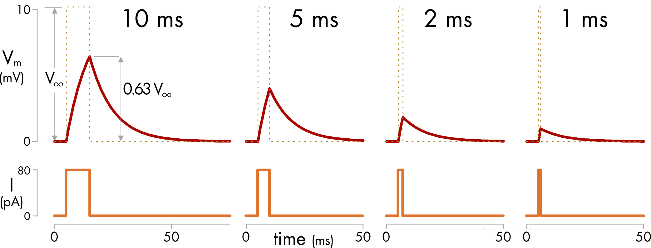
Figure 2 Voltage responses of the RC circuit described in Figure 1 to square pulses of current of different durations. A current pulse of the same duration as the time constant (10 ms) produces a peak voltage response of 0.63 V∞. The expected voltage response if there was no capacitor in the circuit is shown as a dashed line. The peak voltage response declines as the duration of the current pulse decreases.
The membrane capacitance sets a minimum duration for the current signals used in electrical communication between cells. This filter effect means that electrical signaling between cells is many orders of magnitude slower than signaling within conventional electronic circuits. There are other constraints on the speed of electrical signaling between cells but this one is fundamental. No other type of cell membrane with a lower specific capacitance has ever evolved.
In neurons the effect of the membrane time constant is mitigated somewhat by a variety of factors. These include, the complex geometry of neurons, which can reduce the effective time constant, synchronous synaptic activity, which can reduce the membrane conductance and time constant, and active conductances in dendrites, which can amplify the response to synaptic inputs.1 Nonetheless, neuronal signaling is relatively slow. The fastest synaptic inputs are in the low millisecond range, whereas modern computers have cycle times in the gigahertz range. Electrical signaling in computers is roughly a million times faster.
Human brains can currently outperform even the fastest computers on tasks such as visual recognition, which is why we still don’t have self-driving cars. Our nervous system can perform much better than the limitations of individual neurons as electronic components might suggest because of the massively parallel architecture of the brain. Evolution found a way around the relatively slow electrical function of individual cells to maximize system performance.
A tutorial is available on this topic.