Equivalent Components
To create an equivalent circuit of the cell it is first necessary to understand how well each of the biological ‘components’ match their ideal electronic counterparts.
Conductors
The ‘wires’ in biological systems, the conducting elements that connect the various components together, are the intracellular and extracellular electrolyte solutions. In a conventional electronic circuit, the electric current is carried by the flow of electrons in a copper wire. In biological systems electric charge is carried by the movement of ions in the electrolyte solutions inside and surrounding the cell.
When an electric potential difference, or voltage, is applied to an electrolyte solution, the cations (Na+ or K+ ions) migrate toward the cathode (electrode with the negative potential) and the anions (Cl-) migrate toward the anode (electrode with the positive potential) (Figure 1).
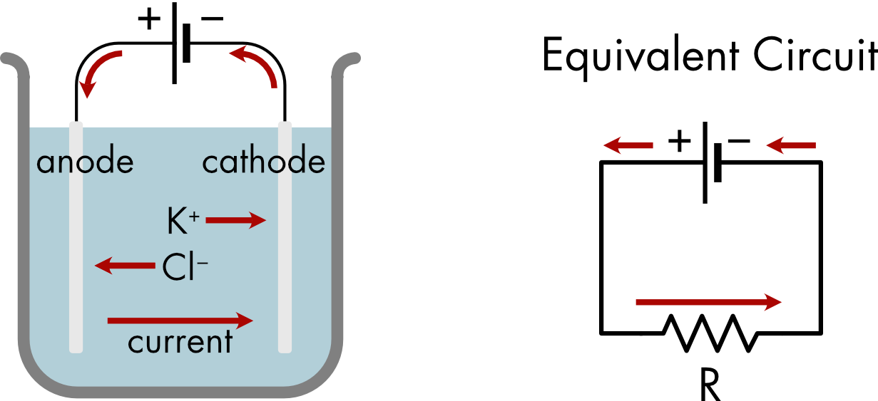
Figure 1 Movement of ions when an electric potential is applied between two electrodes in an electrolyte solution. The beaker is filled with a KCl solution and the two electrodes are connected to a battery. K+ ions migrate towards the cathode and Cl- ions migrate towards the anode. An equivalent circuit is shown on the right. It has two elements, a battery and a conductor.
The setup shown in Figure 1 may not look like a typical electric circuit but an equivalent circuit diagram can be easily drawn. In this circuit there are only two elements: a battery and a conductor. The conductor corresponds to the electrolyte solution which conducts current between the two electrodes.
Like the resistors of electronics systems, the resistance of the intracellular and extracellular electrolyte solutions depends on the geometry of the conducting volume. Biological conductors are generally complex geometrically. The shape of the extracellular region can be torturous as it weaves between cells and its volume is constrained by the tight packing of cells. Current flow within the fine processes of a neuron, the axon and dendrites, can be significantly constrained by the small volumes of intracellular fluid. Intracellular current flow will be further reduced by the presence of any organelles that can block current flow.
The resistivity of the electrolyte solutions also depends on the concentration of ions in solution, although these are generally fixed in biological solutions.
Membrane Conductance
The total conductance of a biological membrane is the sum of the conductance of all the ion channels in the membrane that are open at the time of the measurement.
\[G_{m} = \frac{1}{R_{m}} = \sum_{i = 1}^{N}g_{i}\]
where Gm is the total membrane conductance of the cell, Rm is the total membrane resistance N is the number of open channels in the cell membrane, and gi is the conductance of the individual open channels.
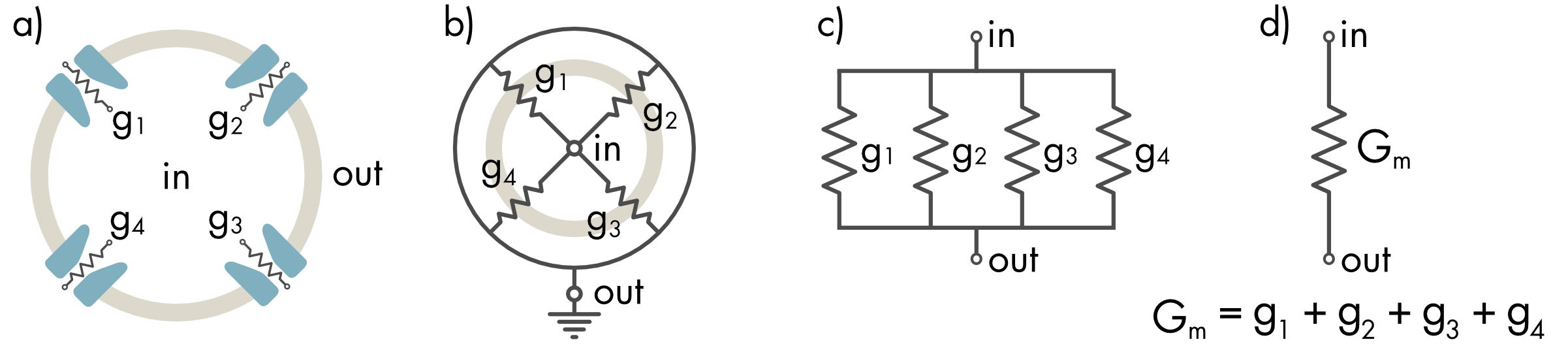
Figure 2 Equivalent circuit for the total membrane conductance (Gm). a) Each open channel is a conductor with conductance gi. b) These conductors are connected at a single node inside the cell (in) and single node outside the cell (out). c) Redrawing this circuit makes it more obvious that the conductors are connected in parallel. d) The individual conductances (gi) can be combined to form a single equivalent component (Gm). The total membrane conductance (Gm) of the cell membrane equals the sum of each individual channel conductance.
An assumption underlying this equivalent circuit is that the interior volume of the cell is isopotential, meaning that everywhere inside the cell has the same electric potential. This is a reasonable assumption for a small round cell. It is rarely true for neurons because of their complex geometry. The model also assumes that the extracellular solution surrounding the cell is isopotential.
It is often convenient to express the membrane conductance as a specific conductance (gm), which is conductance per unit area of membrane. The total cell membrane conductance is the product of the membrane area and the specific conductance,
\[G_{m} = A \cdot g_{m}\]
where A is the area of the cell membrane and gm is the specific membrane conductance. There can be considerable variation in the specific membrane conductance between different cell types. A typical value is gm = 1 pS·µm-2, equivalent to a specific resistance of rm = 1 TΩ·µm2 (or 10 kΩ·cm2).
Membrane Capacitance
Lipid bilayers are very thin non-conducting sheets that surround the cell. Within a limited voltage range the lipid bilayer behaves similarly to an ideal capacitor. The capacitance of the cell membrane is directly proportional to its surface area,
\[C_{m} = A \cdot c_{m}\]
where A is the area of the cell membrane and cm is the specific capacitance, the capacitance per unit area of membrane. The basic structure of lipid bilayers is similar across the entire phylogeny of living organisms and the capacitance of the membrane per unit area of membrane is relatively invariant, approximately 0.01 pF⋅µm-2 (or 1 µF·cm-2).
The capacitance of the cell membrane depends on the permittivity and thickness of the lipid bilayer,
\[C = \frac{\varepsilon_{0}\varepsilon_{r}A}{d}\]
where, ε0 is the permittivity of a vacuum, εr is the relative permittivity of the hydrocarbon core of the lipid bilayer, A is the surface area of the cell membrane, and d is the distance across the core of the lipid bilayer. The cell membrane is a good capacitor in large part because of its molecular dimensions. Capacitance is inversely proportional to the effective thickness of the hydrocarbon core (d), which is tiny, less than 3 nm. The relative permittivity of the hydrocarbon core of the membrane is low (εr = 2.1), which somewhat limits the effectiveness of the membrane as a capacitor. Recall that permittivity is a measure of the polarizability of a material. The hydrocarbon tails of the lipids are not easily polarized.
A consequence of the two-molecule thickness of the membrane dielectric is that there is a very large electric field across the hydrocarbon core of the membrane.
\[E = \frac{V_{m}}{d}\]
where E is the electric field and Vm is the electric potential across the membrane. For a membrane potential of 90 mV and a distance of 3 nm the electric field is 300 kV·cm-1. To put this in perspective, this electric field is roughly an order of magnitude larger than the field required to produce the dielectric breakdown of air, as occurs during lightning.
Transmembrane voltage pulses over approximately 200 mV produce dielectric breakdown, and the formation of transient "pores" in the lipid bilayer, a phenomenon known as electroporation. This places an important constraint on the electrical function of cells — maximum transmembrane voltages are restricted to approximately 150 mV due to instability of the lipid bilayer in larger electric fields.
The lipid bilayer is a very good although not perfect insulator. The specific conductance of a pure lipid bilayer, without any membrane proteins, is approximately 1,000 times lower than that of a typical cell membrane. For a normal cell membrane, the ion channels in the membrane are the primary route of current flow across the membrane.
The hydrocarbon core of the lipid bilayer creates a large energy barrier for ion movement across the membrane. The relative permittivity of water is 80 whereas as the relative permittivity of the hydrocarbon core is 2.1. Ions partition into the aqueous phase in very strong preference to the lipid phase making it very unlikely that ions will diffuse directly across the membrane.
The actual conductance of the lipid bilayer is not quite as low as the permittivity values would suggest because the lipid bilayer is a dynamic structure. The lipid molecules are in constant motion. Water molecules can intersperse into the structure and very rarely create a water defect across the membrane that will transiently lower the energy barrier for ion movement across the membrane (Figure 3). These relatively rare defects account for the higher ion permeation rates across the bilayer than would be expected for a static structure with the same permittivity. Nonetheless, given the very short distances, the constant motion of the bilayer molecules, and the ubiquity of water molecules, it is remarkable how reliable the bilayer is as a barrier to ion permeation.
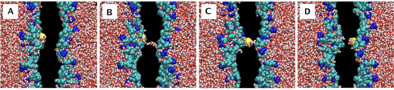
Figure 3 Molecular dynamics simulation of the permeation of a potassium ion across a lipid bilayer. The key event occurs in panel B where a water chain transiently forms across the hydrophobic core of the lipid bilayer. This provides a lower energy pathway for the ion to diffuse across the bilayer. The black region corresponds to the hydrocarbon core of the lipid bilayer. The hydrophobic tails of the lipids are not shown. The hydrophilic heads of the lipid molecules are shown, choline groups in blue, and the phosphate and glycerol groups in cyan. A potassium ion is labeled yellow and water molecules in red and white. Figure adapted from (Gurtovenko & Vattulainen, 2007).
Numerical Example
For a 50 µm diameter cell the surface area of the cell membrane is given by,
\[\text{area} = 4\pi r^{2} = 7,854\ \text{μ}\text{m}^{\text{2}}\]
If the membrane has a specific conductance of gm = 1 pS·µm-2 then the membrane conductance is,
\[\begin{aligned}G_{m} &= A \cdot g_{m}\\\\[-2ex] &= 7,854\ \times 10^{- 12}\\\\[-2ex] &= 7.9\ \text{nS}\end{aligned}\]
The membrane resistance is given by,
\[R_{m} = \frac{1}{G_{m}} = 127\ \text{MΩ}\]
If the specific capacitance is 0.01 pF⋅µm-2 then the total membrane capacitance is,
\[\begin{aligned}C_{m} &= A \cdot c_{m}\\\\[-2ex] &= 7,854 \times 0.01\\\\[-2ex] &= 79\,\text{pF}\end{aligned}\]