Tutorial: RC Circuits 1
In this tutorial you will examine the electrical properties of the RC circuit. The RC circuit is used to model the passive electrical properties of small cells with simple geometry. In these cells the voltage is the same everywhere inside the cell. This property is known as electrical isopotentiality. Cells that are isopotential or close to isopotential are said to be electrically compact.
Experiment 1: Basic Circuit Properties
In this experiment the response to a constant current injection will be examined in three circuits (Figure 1). Circuit 1 has a single resistor leading to ground. Circuit 2 has a single capacitor leading to ground. Circuit 3 is an RC circuit in which a resistor and capacitor are wired in parallel and lead to ground.
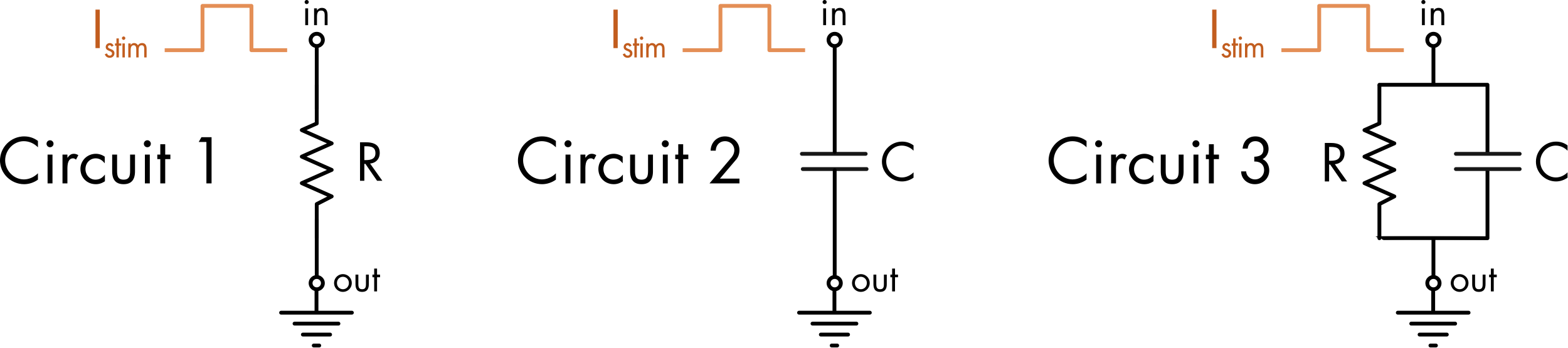
Figure 1 The effect of a stimulus current, Istim = 0 to 100 pA, can be compared in three circuits. The values for the resistor and capacitor are R = 100 MΩ and C = 100 pF, respectively. The graphs show voltage (V), the stimulus current (Is), the current flowing in or out of the capacitor (Ic) and the current flowing through the resistor (Ir). Movement of the mouse over the graph displays cursors, and the values at the cursors for each graph are shown in the right panel. You can also use the left and right arrow keys for finer movement of the cursors, and shift+arrow keys for larger movements.
For Circuit 1, in response to a step increase in the stimulus current there is a step increase in the voltage. The voltage returns to zero as soon as the current injection ceases. For Circuit 2, the voltage rises linearly while current is being injected into the circuit and then remains at this new stable voltage value when current flow ceases. For Circuit 3, the voltage response to current injection is a combination of the behaviors seen in the other two circuits. At the onset of the current step the instantaneous rate of change of the voltage is the same as that seen in Circuit 2 (Figure 2). At longer time points (>50 ms) the voltage approaches the same stable voltage value as seen for Circuit 1. This happens because at the onset of the current step the bulk of the stimulus current flows onto the capacitor whereas at later time points most of the current flow is through the resistor.
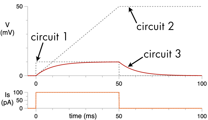
Figure 2 The response to a 100 pA stimulus current, for circuit 1 (dashed line), circuit 2 (dashed line) and circuit 3 (red line).
Questions:
To make it easier to answer these questions duplicate this page and then tear off the tab and place adjacent to this page so that you can run the simulations while also reading the questions.
- What equation describes the change in voltage in Circuit 1 in response to a current step?
- Calculate the change in voltage in Circuit 1 in response to a 100 pA current step. Confirm your answer by measuring the value from the graph (mouse over the graph to measure values).
- What equation describes the voltage change when there is only a capacitor in the circuit? Calculate the rate of change of the voltage in response to current injection when Istim = 100 pA and C = 100 pF. Check your answer against the graph.
- For Circuit 2, calculate the final change in voltage in response to a 100 pA current stimulus applied for 50 ms. Check your answer using the graph.
- Why does the voltage stay high after the cessation of the current stimulus at time = 50 ms in Circuit 2?
- What equation describes the voltage response to a current step at infinite time when there is both a capacitor and resistor in parallel?
- What is the change in voltage in response to the current stimulus at infinite time in Circuit 3? Check your answer against the graph.
- Why is the voltage response to a 50 ms current injection so much smaller in Circuit 3 than in Circuit 2?
- Why at the onset of a current step in an RC circuit does the bulk of the stimulus current flow onto the capacitor, whereas at later time points most of the current flows through the resistor?
A key thing to understand from this simulation experiment is that the membrane conductance acts to limit changes in voltage in response to current flow across the membrane. In the absence of any conductance the membrane potential increases in an unconstrained fashion in response to current flow due to charging of the membrane capacitance. As discussed previously ion channels probably evolved very early in cellular evolution in order to stabilize membrane potentials.
Experiment 2: Unknown Cell Membrane Properties
A common experimental situation is that you wish to determine the passive electrical properties of a cell and the only tool you have is the ability to inject square pulses of current into the cell.
Question:
- Determine the input resistance (\(R_{m}\)) and total capacitance (\(C_{m}\)) of this cell by injecting current pulses.
Figure 3 A cell with unknown input resistance and capacitance. Modify current injection parameters to determine these values.