Leak Conductance and Resting Membrane Potential
Unlike the simple RC circuit described in the previous section, the voltage inside a cell relative to ground will have some negative value at rest, in the range -60 to -90 mV depending on the cell type. This value is known as the membrane voltage (\(V_{m}\)) or membrane potential. The conductance of the cell membrane at the normal resting membrane potential is known as the leak conductance (\(G_{L}\)). This conductance is almost always relatively small, since this minimizes the rate at which ions leak in or out of the cell, thereby minimizing the metabolic cost of maintaining the ion gradients in the cell.
One typical way to model the leak conductance is to lump all the channels in the cell that are open at rest into a single conductance \((G_{L})\) (Figure 1). The voltage determining current flow through these channels is given by the driving force \((V_{m} - V_{L})\), where \(V_{L}\) is the leak potential. This is the membrane voltage at which net current flow through \(G_{L}\) is zero. In a typical model this value is adjusted to give the desired resting membrane potential (\(V_{m}\)) for the cell.
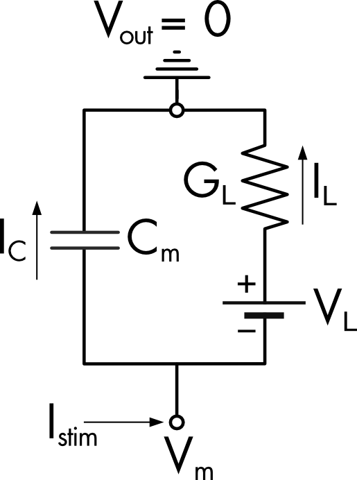
Figure 1 Equivalent circuit of a small cell with a resting leak conductance. The extracellular potential is assumed to be zero. The voltage difference across the membrane is the membrane potential (Vm). The leak potential (VL) is modeled as a battery in series with the leak conductance (GL).
Model using specific membrane conductance and capacitance
Typically models of neuronal excitability use specific capacitance and specific conductance to describe the membrane properties i.e., capacitance or conductance per unit area of membrane. This makes it simpler to change the size of the cell, or cell compartment, in the model and facilitates comparison between models with different cell sizes.
When the specific membrane conductance (\(g_{L}\)) and capacitance \(\left( c_{m} \right)\) are used in equations to model the cell’s electrical function it is necessary to scale these values using the membrane area of the cell \((A)\). It is also necessary to use the driving force \((V - V_{L})\) to describe current flow through the leak conductance. The equation describing current flow across the membrane is given by,
\[I_{\text{stim}} = A{\overline{c}}_{m}\frac{dV}{dt} + A{\overline{g}}_{L}(V - V_{L})\]
This can be simplified by calculating the total cell capacitance \((C_{m})\) and conductance \((G_{L})\),
\[I_{\text{stim}} = C_{m}\frac{dV}{dt} + G_{L}\left( V - V_{L} \right)\]
Rearranging,
\[ \frac{dV}{dt} = (I_{\text{stim}} - G_{L}(V - V_{L}))/C_{m}\ \tag{1} \]
Equation 1 can be solved using any of the methods described in Appendix 2. Figure 2 shows the voltage response of the model cell to hyperpolarizing and depolarizing current steps. This model gives a reasonable approximation of the voltage response to small, injected currents in a typical cell, since the voltage responses of a typical cell around the resting membrane potential are approximately linear. With larger current injections the non-linear behavior of a real cell’s membrane conductance systems will become increasingly apparent. This will require a more complex model incorporating voltage-gated channels to describe accurately.
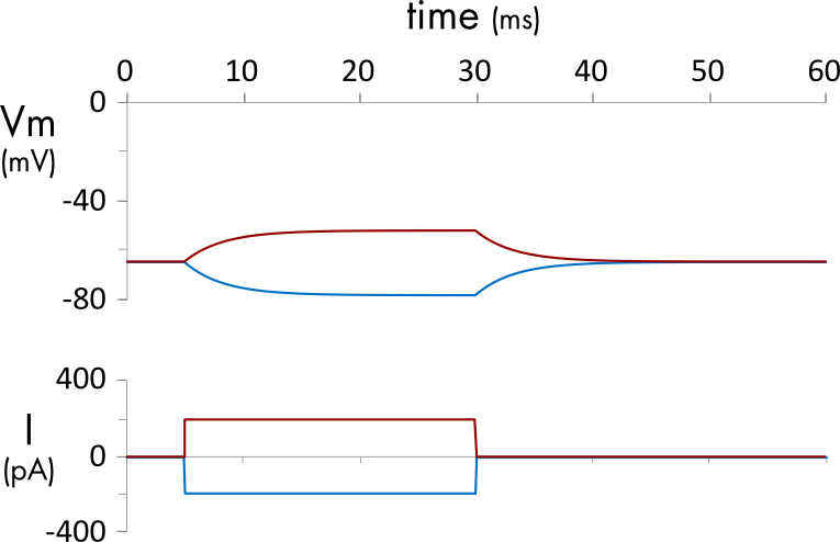
Figure 2 Response of a 40 μm diameter spherical cell with a resting membrane potential of -65 mV to 200 pA (red) and -200 pA (blue) current injections. The cell membrane has a specific capacitance of 0.01 pF/cm2 and a specific leak conductance of 3.0 pS/µm2.
A link to a Jupyter Notebook (ForEulerLeak.ipynb) solving Equation 1 can be found at the bottom of the page.
Units
It is critical to use the correct units to describe the cell membrane capacitance and conductance to obtain meaningful results.
The dimensions of mammalian cells are typically given in microns (µm), so it makes sense to describe specific membrane properties per µm2 for these cells. It has, however, been traditional to give specific properties per cm2, following Hodgkin and Huxley who studied the unusually large squid giant axon.
A typical value used for the specific capacitance of the cell membrane \(({\overline{c}}_{m})\) is 0.01 pF⋅µm-2 (1 μF⋅cm-2). For a cell with a diameter of 40 μm, assuming that it is perfectly spherical, the surface area of the cell membrane is \(A = 4\pi r^{2}\) = 5,027 μm2 (5.03×10⁻⁵ cm2). The total membrane capacitance (\(C_{m})\) of the cell is,
\[C_{m} = \text{A\ }{\overline{c}}_{m} = \ 50.3\ \text{pF}\]
A smaller cell, having a smaller membrane area, will have a smaller total cell capacitance \((C_{m})\) than a larger cell, even though it has the same specific capacitance \(({\overline{c}}_{m})\).
Unlike membrane capacitance, which is relatively constant for all cells, due to the similar chemical makeup of the lipid bilayer, the specific leak conductance is quite variable between different cells, reflecting large differences in the patterns of ion channel expression. Hodgkin and Huxley used a specific resting leak conductance \(({\overline{g}}_{L}\)) of 3.0 pS⋅µm-2 (0.3 mS⋅cm-2) in their original model. For a 40 μm diameter cell with this specific conductance the total cell leak conductance \((G_{L})\) would be,
\[G_{L} = \text{A\ }{\overline{g}}_{L} = \ 15.1\ \text{nS}\]
A typical single channel conductance value is 10 pS, so for this cell approximately 1,500 leak channels will be open at any one time.
Model Sanity Check
It is possible to do some simple sanity checks to confirm that the units have been implemented correctly in the model described above. Two easily measured properties of the passive response of the cell can be calculated directly.
The change in the steady state voltage in response to a 200 pA stimulus current \({(I}_{\text{stim}})\) injection is given by Ohms law,
\[\Delta V_{\infty} = \frac{I_{\text{stim}}}{G_{m}} = \ 200 \times 10^{- 12}/15.1 \times 10^{- 9} = 13.2\ mV\]
The membrane time constant for the cell is,
\[\tau = \frac{Cm}{Gm} = (50.3 \times 10^{- 12})/(15.1{\times 10}^{- 9}) = 3.33\text{\ ms}\]
The time constant can also be computed directly from the specific capacitance and conductance values,
\[\tau = \frac{{\overline{c}}_{m}}{{\overline{g}}_{L}} = (0.01\ pF \cdot µm^{- 2})/\ (3.0\ pS \cdot µm^{- 2}) = 3.33\text{\ ms}\]
Jupyter Notebook
Right click on the link to download a JupyterLab file (select ‘Save Link As…’). The files can be run locally using JupyterLab or in the cloud using Google Colab. Upload the files into Colab by selecting ‘File>Upload notebook’.