Membrane Potential – Equivalent Circuits
The conductance of the cell membrane depends on the number and type of ion channels in the membrane. There are channels that are selective for each of the major ions (potassium, sodium, chloride, and calcium) found in the electrolyte solutions inside and surrounding the cell. Each type of channel can be viewed as a separate conductance system even though the currents that flow through each system ultimately sum into a single membrane current.
Model Cell with a Potassium Ion Conductance
In a typical cell, most of the channels that are open at rest are potassium channels. An equivalent circuit of a cell with only potassium channels is shown in Figure 1.
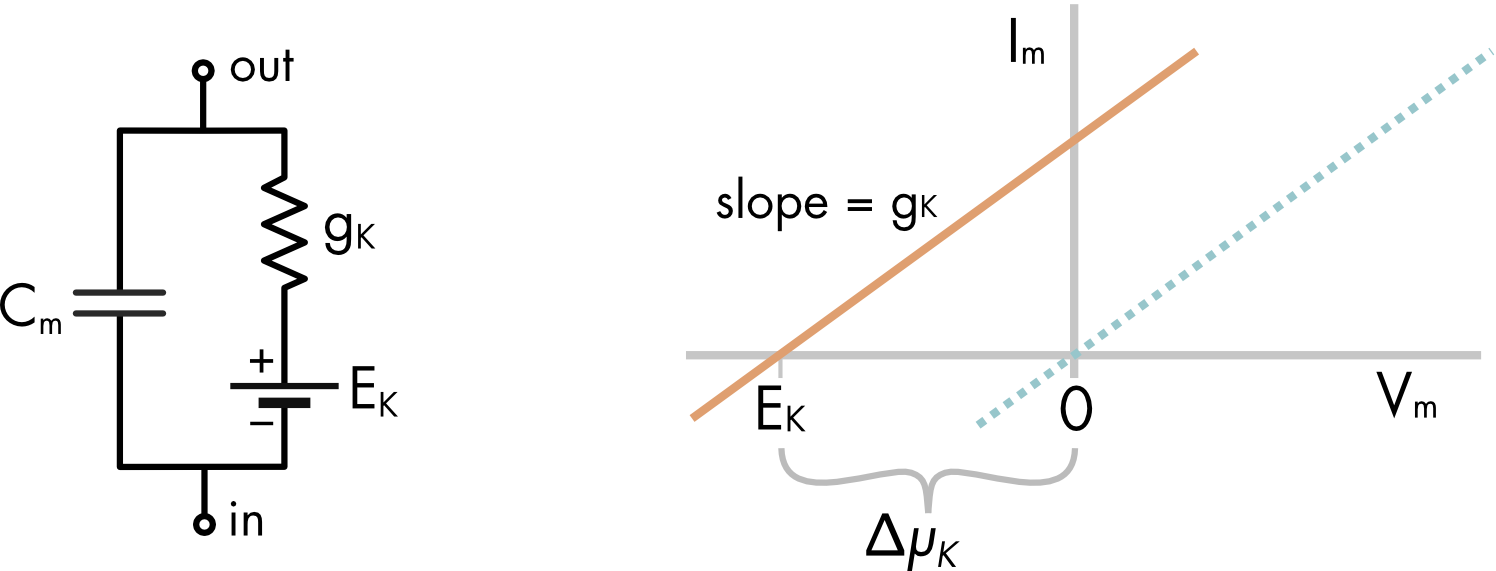
Figure 1 Equivalent circuit of a cell with only a potassium conductance. EK is the equilibrium potential for potassium ions and ΔμK is the chemical potential difference for potassium ions. The I-V relationship for the potassium conductance is shifted to the left by a voltage equivalent to the chemical potential difference for potassium ions. The x-axis is the membrane potential (Vm) and the y-axis is the membrane current (Im).
The circuit shown in Figure 1 is a parallel RC circuit with a battery in series with the potassium conductance. If there were no battery it would be expected that current flow would be zero when the voltage across the membrane was zero (see the blue dotted line in the accompanying I-V curve). Instead, for a potassium conductance the zero current point occurs at the equilibrium potential for potassium ions (orange line). This is the voltage where there is no current flow carried by the potassium ions because the potassium ions are at electrochemical equilibrium. When the membrane potential is more positive than EK potassium ions flow out of the cell, carrying an outward current, when the voltage is more negative than EK potassium ions flow into the cell, carrying an inward current. By convention, a current flowing out of the cell is a positive current and an inward current is a negative current.
Recall that the equilibrium potential for monovalent cations is equal to the chemical potential expressed in volts rather than joules per mole,
\[E_{K} = \frac{\text{Δμ}_{K}}{F}\]
where F is the Faraday constant, which converts the units of joule per mole to volts (or joule per coulomb) and ΔμK is the chemical potential difference for potassium ions. The unequal distribution of potassium ions across the cell membrane creates a greater chemical potential for potassium ions inside the cell than outside, which functions like a battery.
To describe the I-V curve for the potassium conductance Ohm’s law is modified to take account of the chemical potential difference across the cell membrane,
\[I_{K} = g_{K}\left( V_{m} - E_{K} \right)\]
where IK is the current carried by potassium ions, gK is the potassium conductance and (Vm – EK) is the driving force acting on the potassium ions, which is a combination of both the electric potential difference across the membrane (Vm) and the chemical potential difference (\(\text{Δμ}_{K}\)).
Cell with Potassium and Sodium Ion Conductances
The membrane potential of a typical cell is more positive than the potassium equilibrium potential which implies that other ions in addition to potassium ions contribute to setting the membrane potential. Typically, these ions are sodium and chloride. In some cells the chloride ions are distributed passively and make no significant contribution to the resting membrane potential. An equivalent circuit with just a potassium and sodium conductance can account for the membrane potential in these cells.
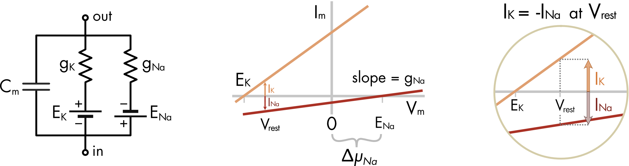
Figure 2 Equivalent circuit of a cell with potassium and sodium conductances. A plot of the I-V curves shows that sodium conductance is smaller than the potassium conductance. At the resting membrane potential (Vrest) the outward potassium current (IK) has the same magnitude as the inward sodium current (INa). This can be seen more clearly in the righthand panel. Note that the chemical potential differences for each ion species have opposite signs and this is reflected in the opposite polarity of the batteries associated with the two conductance systems. EK is the equilibrium potential for potassium ions and ENa is the equilibrium potential for sodium ions.
At the resting membrane potential there is no net current flow across the cell membrane and the sum of currents equals zero,
\[I_{K} + I_{\mathit{Na}} = 0\text{ }\]
where,
\[\begin{aligned}I_{K} &= g_{K}\left( V_{m} - E_{K} \right)\\\\[-2ex] I_{\mathit{Na}} &= g_{\mathit{Na}}\left( V_{m} - E_{\mathit{Na}} \right)\end{aligned}\]
The driving force is considerably larger for sodium ions than for potassium ions at the resting potential. The potassium and sodium currents are equal because the sodium conductance is much smaller than the potassium conductance, as seen by the shallower slope of the I-V curve for sodium ions compared to potassium ions (Figure 2).
For mammalian cells the membrane potential will usually fall somewhere between the equilibrium potential for K+ and Na+ ions (Figure 3). Exactly where it lands depends on the relative magnitude of the potassium and sodium conductances.
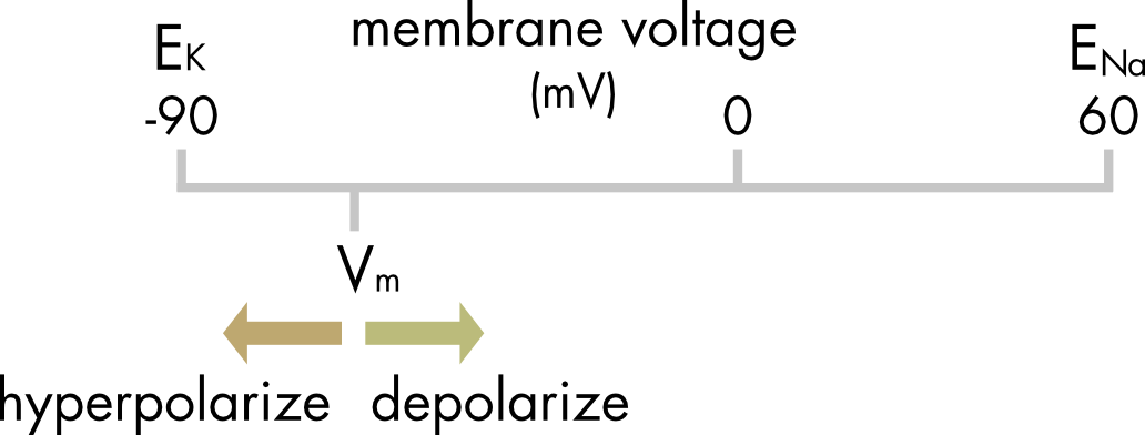
Figure 3 Relationship between EK, ENa and Vm in a typical cell at rest.
Currents that move the membrane potential to more positive potentials are said to depolarize the membrane and currents that make the membrane potential more negative are said to hyperpolarize the membrane.
Cell with a Leak Conductance
The membrane conductance of a cell at rest is small. This saves energy by minimizing ion fluxes leaking into and out of the cell. It is often hard to accurately measure the contribution of each ion to the resting conductance. In contrast it is usually straightforward to measure the total membrane conductance. A simplifying assumption that is often made is to lump together all the ion channels open at rest and call the sum of conductances a leak conductance. The reversal potential of the leak conductance is then set to the membrane potential. In the absence of any other conductances the membrane potential of the model will remain at the resting membrane potential.
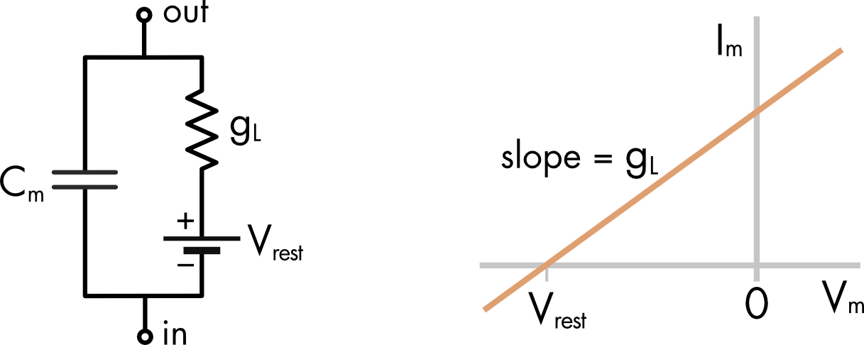
Figure 4 Equivalent circuit of a cell with a leak conductance. The reversal potential of this conductance is Vrest, the resting membrane potential.
Current flow through the leak conductance is given by,
\[I_{L} = g_{L}\left( V_{m} - V_{\text{rest}} \right)\]