Electrical Components and Circuits
Perhaps surprisingly, the modern era in the study of electricity began with a biologist, the Italian physician Luigi Galvani, who in 1780 described ‘animal electricity’ in frog legs. Alessandro Volta, a physicist, in his efforts to discredit aspects of Galvani’s work, invented the battery in 1799 (originally known as the voltaic pile). Volta’s design was inspired by analogy to the electric organ of electric fish. Volta’s batteries were used to create the first electric circuits, and this led to Georg Ohm’s description in 1827 of Ohm’s law, a fundamental law in electric circuit theory.
A key step in understanding of the function of electrically excitable cells like neurons and muscle cells was the recognition that the electrical function of these biological systems could be modeled using electric circuit theory. This section describes the basic concepts of electric circuit theory required to understand the electrical function of cells.
Charge
Charge (q) is the fundamental unit of electrical function. The unit of electrical charge is the coulomb (C). The charge on a single electron is known as the elementary charge (e) and is equal to -1.602×10⁻¹⁹ C.
In biological systems the charge carriers are anions and cations in solution, known collectively as electrolytes. The charge on a single ion is given by
\[\ q = ze\]
where z is the valence of the ion. Monovalent cations such as sodium ions have a charge of +e and monovalent anions such as chloride ions have a change of -e. Divalent cations such as calcium ions have a charge of +2e.
The unit for charge (coulombs) can be confusing since it does not directly correspond to either the elementary charge or to the charge on one mole of elementary charge.
The Faraday constant is the amount of charge on one mole of electrons,
\[\begin{aligned}q &= \text{N}_{\text{A}}e\\\\[-2ex] &= 6.033 \times 10^{23} \times 1.602 \times 10^{- 19}\\\\[-2ex] F &= 96,485\,\ \text{C} \cdot \text{mol}^{- 1}\end{aligned}\]
where NA is the Avogadro constant and F is the Faraday constant.
The Faraday constant is a conversion factor used to switch from the number of moles of electrons to the number of coulombs or vice versa.
Electric Potential
The electric potential (\(\phi\)) is defined as,
\[\phi = \frac{U_{E}}{q}\,\text{ \ \ \ \ \ \ }\left( \text{V)\ or\ (J} \cdot \text{C}^{- 1} \right)\]
where the electric potential energy (UE) has the units of joules (J) and the electric potential (\(\phi\)) has the units of volts (V) or joules per coulomb (J⋅C-1). The electric potential is the electric potential energy per unit charge.
The electric potential difference (ΔV) is the difference in the electric potential at two points A and B,
\[\Delta V = \phi_{B} - \phi_{A}\]
The electric potential difference (ΔV or V) is the property most likely to be measured experimentally. A voltage difference can be recorded with a voltmeter. Typically, one point is defined as ground, or zero volts, and the electric potential difference, or voltage, is recorded relative to that point.
The relationship between electric potential energy (UE) and the electric potential difference (ΔV) is analogous to the relationship between Gibbs free energy (G) and the chemical potential difference (Δμ). The electric potential energy is an extensive property of the system, as is the Gibbs free energy. The electric potential difference and the chemical potential difference are both intensive properties and do not depend on the amount of substance in the system. This difference can be illustrated by considering a small 12-volt battery and a large car battery. Each battery generates the same electric potential difference (nominally 12 volts), but the large car battery stores much more electric potential energy than the small battery.
Current
Current (I) is defined as the amount of charge flowing per unit time,
\[I = \frac{\text{dq}}{\text{dt}}\]
Current has the units of amperes (A). One ampere is defined as one coulomb per second.
\[1\text{A\ =\ 1C}\text{s}^{\text{-1}}\]
Conductors and Resistors
Current flows through conductors and resistors. The distinction between these elements is a matter of degree. A good conductor, like a copper wire, has a low but non-zero resistance. Conversely, even the largest resistor has some conductance, or the circuit would be open (no path for current flow). Resistance (R) is measured in the units of ohms (Ω). Conductance (G) is the inverse of resistance and is expressed in the units of siemens (S).
\[G = 1/R\]
Conductance rather than resistance is often used to describe the properties of biological conductors because the value of multiple different conductances in parallel, such as channels in a membrane, can be easily summed to give the total membrane conductance.
For a simple resistor its resistance depends on its geometry and the properties of the material from which it is made,

where R is resistance, ρ is the electrical resistivity of the material, l is the length and A is the cross-sectional area.
There is a close analogy between water flow through a pipe and current flow through a resistor. The bigger the pipe the lower the resistance and the longer the pipe the higher the resistance.
Ohm’s Law
Ohm’s law describes the linear relationship between voltage and current for an ideal resistor.
\[I = V/R\]
It can also be expressed in terms of conductance,
\[I = GV\]
An I-V curve is a graph of the dependence of current flow on the voltage across a given element. For an ideal resistor the I-V curve is linear, and the slope of the I-V curve is 1/R or G (Figure 1).
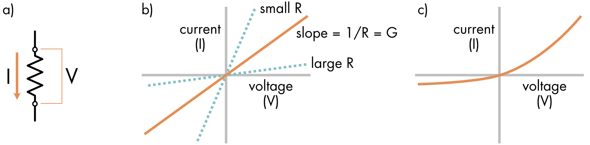
Figure 1 a) A voltage (V) is placed across a resistor causing a current (I) to flow. b) Current-voltage relationship (I-V curve) of an ideal resistor. Current flow is directly proportional to voltage and the I-V curve is linear. The value of the resistor can be determined from the slope of this relationship (slope = 1/R). A shallower slope implies greater resistance to current flow i.e., it is a larger resistor. A smaller resistor will produce a steeper slope. c) Non-ohmic conductors have nonlinear I-V curves.
Ohm’s law is an empirical relationship. While true for most metals, biological conductors such as ion channels do not necessarily obey linearity. These non-ohmic conductors are said to rectify. The conductance changes as the voltage changes (Figure 1C).
Kirchhoff’s laws
Kirchhoff’s laws describe key properties of electric circuits. Kirchhoff’s current law states that the sum of the currents flowing into a node of a circuit must equal the sum of currents flowing out of the node (Figure 2).
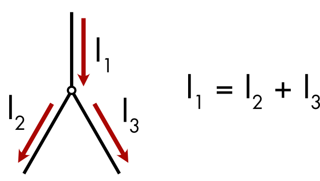
Figure 2 Kirchoff’s current law. A node in the circuit is indicated by a small circle.
This is equivalent to saying that the sum of all the currents flowing into and out of a node in the circuit should equal zero.
\[\sum_{k = 1}^{n}I_{K} = 0\]
This is a special case of the law of conservation of electric charge.
Kirchhoff’s potential law states that the sum of the potentials across all the elements in a circuit must equal zero (Figure 3).
\[\sum_{k = 1}^{n}V_{K} = 0\]
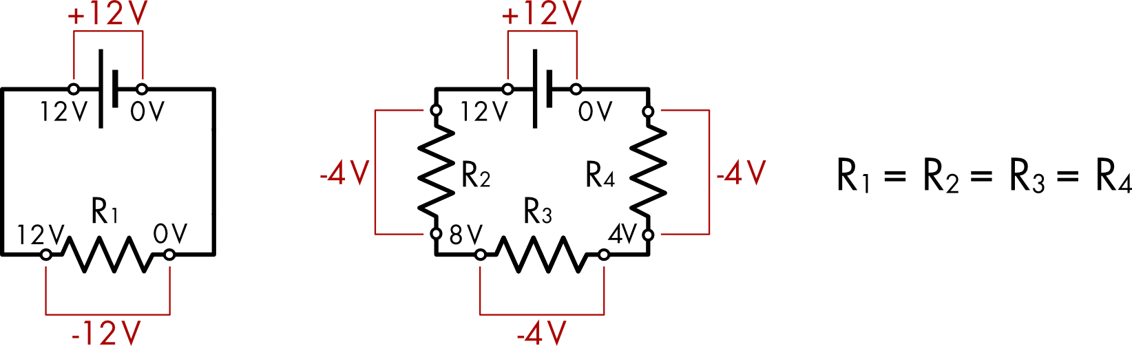
Figure 3 Kirchoff’s potential law. (left) A 12 volt battery in series with a single resistor. (right) A 12 volt battery in series with three identical resistors.
When there is a single resistor in the circuit the voltage drop across the resistor equals the full potential of the battery. If three identical resistors are in series in the circuit then the voltage drop across each resistor will be only 1/3 of the potential generated by the battery.
Capacitance
Capacitance (C) is a measure of the ability of a capacitor to store an imbalance of charge.
\[C = \frac{q}{V}\]
It is measured in the units of farads (F). One farad is defined as one coulomb per one volt.
\[\text{1 farad }\left( \text{F} \right)\text{ = }\frac{\text{1 coulomb }\left( \text{C} \right)}{\text{1 volt }\left( \text{V} \right)}\text{ }\]
The amount of charge stored depends on the capacitance of the capacitor and the magnitude of the applied voltage.
\[q = CV\]
Current flow into or out of a capacitor depends on the rate of change of the voltage,
\[I_{C} = \frac{\text{dq}}{\text{dt}} = C\frac{\text{dV}}{\text{dt}}\]
where IC is the current flowing in or out of the capacitor, C is the capacitance of the capacitor and dV/dt is rate of change of the voltage across the capacitor. If dV/dt = 0, i.e. the applied voltage is constant, then there is no capacitive current flow. Whereas the potential energy that produces current flow through a resistor is dissipated as heat, current flow into a capacitor is stored as electric potential energy that can be released at some later time.
A typical parallel plate capacitor is a simple device. It is a sandwich of two conductive metal plates separated by an insulating material called the dielectric (Figure 4). Wires attach to each conductive plate.
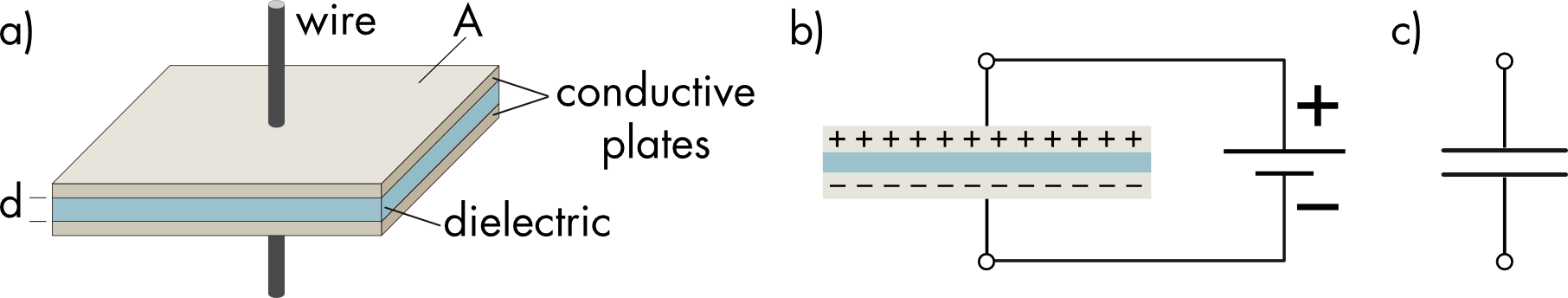
Figure 4 a) Structure of a parallel plate capacitor. Two conductive plates sandwich a dielectric. Each conductive plate is attached to a wire. b) When a battery is attached to the capacitor charge flows into the capacitor where it is stored. The amount of charge stored depends on the voltage and the capacitance of the capacitor. c) Symbol for a capacitor in a circuit.
The capacitance (C) of a parallel plate capacitor is proportional to the permittivity of the dielectric and the area of the plate. It is inversely proportional to the distance between the conductive plates.
\[C = \frac{\varepsilon_{0}\varepsilon_{r}A}{d}\]
where, ε0 is the permittivity of a vacuum and εr is the relative permittivity (or dielectric constant) of the dielectric material. A is the surface area of the capacitor and d is the separation distance between the conductive plates.
The effect of surface area on capacitance is obvious, increasing area gives more material on which to store charge. The effect of separation distance is more complicated. The charges on each of the two plates create an electric field. The electric field (E) is independent of the separation distance.
\[E = \frac{q}{\text{εA}}\]
The electric potential between the plates does depend on separation distance,
\[V = Ed\]
Since the electric field is constant for a given amount of charge on the plates reducing the separation distance reduces the voltage. A smaller distance means that more charge can be stored for a given applied voltage (from \(C = q/V\)) i.e. there is increased capacitance.
Commonly used dielectric materials are insulators, they have a very low conductance, but also have a high relative permittivity i.e. they are easily polarized. Relative permittivity is a measure of the permittivity or polarizability of the dielectric relative to a vacuum (ε0 = 8.854 × 10⁻¹² F⋅m-1).
Polarization of the dielectric by an applied voltage decreases the electric field between the two plates allowing more charge to accumulate for a given voltage than would be possible if the dielectric had a low permittivity (Figure 5).
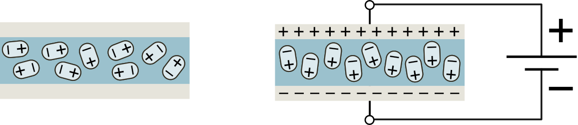
Figure 5 In the absence of an applied voltage (left) the dipoles within the dielectric are randomly ordered. Application of a voltage across the capacitor causes the dipoles to align with the electric field, reducing the electric field created by the accumulation of charge on the conductive plates.
An analogy can be drawn between a parallel plate capacitor and the lipid bilayer of the cell separating the two electrolyte solutions inside and outside the cell. The lipid bilayer does not pass ions and creates a sheet of electrical insulation around the cell. This corresponds to the dielectric of a capacitor. The electrolyte solutions on either side of the lipid bilayer correspond to the two conductive plates.
Parallel and Series
Circuit elements can be arranged either in series or parallel (Figure 6).
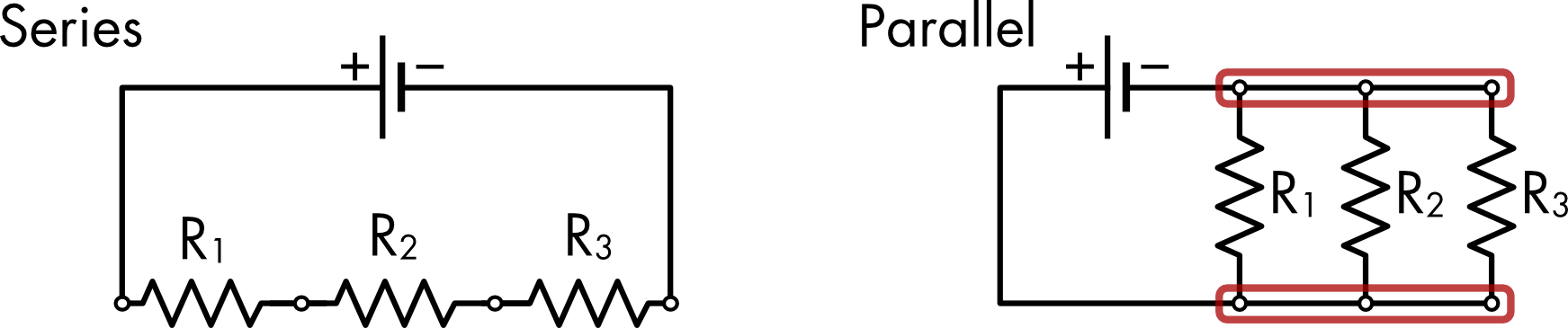
Figure 6 Three resistors connected to a battery either in series or in parallel. In the series arrangement the voltage difference across each resistor is 1/3 of the total voltage, assuming the resistances are equal. In the parallel circuit the nodes circled in red comprise a single node. Each resistor sees the same voltage drop.
For the series arrangement the total resistance in the circuit is given by,
\[R_{\text{total}} = R_{1} + R_{2} + R_{3}\]
For the parallel arrangement,
\[{1/R}_{\text{total}} = {1/R}_{1} + {1/R}_{2} + {1/R}_{3}\]
however, the conductance values sum directly,
\[G_{\text{total}} = G_{1} + G_{2} + G_{3}\]
Capacitance also sums directly when the capacitors are connected in parallel.
Circuit Symbols
The following circuit symbols will be used in subsequent sections.
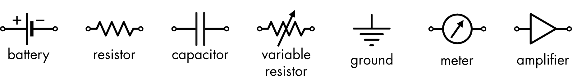
The conductance of some channels can change depending on voltage and time. This is represented as a variable resistor. One point in the circuit is often defined as ‘ground’, this is the zero-voltage point. All voltages in the circuit are referenced relative to this point. Amplifiers are used to increase the small voltage signals or currents that flow in biological systems so that they can be detected and recorded. Meters are used to display and record these voltage or current signals.