Ion Channel Gating
If all the channels in an electrically excitable cell were always open, the membrane would have a very large conductance. Ions would flow down their concentration gradients faster than the Na,K-ATPase pump could pump them back out again and the cell would die. In general, most of the ion channels in the cell membrane are in a non-conducting state most of the time. The transition between the non-conducting and conducting states is termed gating. This term refers to the idea that there is a physical “gate” that blocks access to the channel. Although this term was derived long before structures for ion channels were available, it still provides a reasonable description of the process.
Channels can be gated by several different stimuli including: changes in membrane voltage, changes in intracellular Ca2+ or H+ ion concentrations, binding of G-proteins to the channel and covalent modification of the channel by phosphorylation. A given channel will only be gated by a subset of these different stimuli. In electrically excitable cells the most important gating mode is voltage-dependent gating in which the gate opens or closes in response to changes in membrane voltage.
Voltage-Dependent Ion Channels
Kinetic Properties of Voltage-Dependent Channels
Voltage-gated channels typically have three distinct states: open, closed, and inactivated (Figure 1). Although the closed and inactivated states are functionally similar in that neither state allows the passage of ions through the channel, they are physically quite different states of the channel. The open state is the state during which ions can flow through the pore.
The rate of transition between these states depends on the membrane voltage. As a consequence, the rate constants that describe the transitions between these kinetic schemes are not actually constant but change with membrane voltage and are known as voltage-dependent rate constants.
Figure 1 (left panel) Simple kinetic scheme for a typical voltage-gated ion channel with three channel states: closed, open and inactivated. (right panel) Time course of the fraction of channels that are open during step changes in membrane voltage.
For a typical voltage-gated ion channel at resting membrane potentials (Vm = -80 mV), almost all the channels are closed, because the rate constants strongly favor the transition from the open and inactivated states back to the closed state. Following a step change in membrane potential to +10 mV, the rate constants rapidly change, and the channels move from the closed state to the open state. This movement is known as activation. For most voltage-gated channels, the time course of activation is sigmoidal (S-shaped) indicating a more complex kinetic scheme than that shown in Figure 7, with multiple closed states before the open state.
If the membrane potential is moved quickly back to rest, the channels move from the open state back to the closed state. This is known as deactivation.
If the voltage step to +10 mV is maintained for a prolonged period, the channels leave the open state and enter the inactivated state. This is known as inactivation. If, after most of the channels become inactivated, the membrane potential is returned to the resting value, the channels move from the inactivated state back to the closed state. This is known as recovery from inactivation.
It is important to recognize that the rate constants controlling the transitions between these different states vary dramatically among different voltage-gated channels. Unlike the pore properties, which are essentially invariant over large evolutionary distances, the kinetic properties of these channels have diversified significantly in eukaryotes. Some channels will activate and inactivate in a few milliseconds whereas other channels take minutes to inactivate and some do not inactivate at all. This will be discussed in more detail in a later chapter.
Structure of Voltage-Dependent K+ Channels
The minimal K+ channel subunit described above has only two membrane spanning domains. This is sufficient for the channel to function as a pore for the selective movement of K+ ions across the membrane. Typically, K+ channels are more complex and have additional regions that are responsible for the channel gating and other functions or properties of the channel (Figure 2). Voltage-gated K+ channels generally have six membrane spanning domains (S1-S6), the last two of which (S5 and S6) correspond to the two membrane spanning domains of the minimal K+ channel. The amino- and carboxyl-terminals of the protein are intracellular.
Figure 2 Six membrane spanning regions of a typical voltage-gated K+ channel. A key feature is the S4 domain, which has several positively charged residues and acts as the voltage sensor.
Activation
A voltage-gated channel must have a voltage sensor, some part of the channel that can sense changes in membrane potential and this sensor must contain charged residues, since this is the only way that the protein can “see” a change in membrane voltage. The S4 helix of the channel acts as the voltage sensor in voltage-gated channels. The S4 region has a highly unusual structure for a membrane protein. Like a typical membrane spanning region, it is generally hydrophobic but, almost uniquely, it contains four or more positively charged lysine or arginine residues at every third position interspersed with the hydrophobic residues (Figure 2). It is these positive charges that sense the change in membrane potential and it is their movement within the membrane that triggers the conformational change that opens the gate.
Figure 3 Structure of a voltage gated K+ channel. The four subunits are each marked with a different color.
The channel has a core domain that is comprised of the S5 and S6 helices plus the selectivity filter (Figure 3). This region mediates ion permeation across the cell membrane. Attached to this core is the voltage sensor domain, which is comprised of the S1-S4 helices. This domain is linked to the gate of the core channel via the S4-S5 linker so that movement in the S4 domain is translated into movement in the gate of the channel.
In response to membrane depolarization the S4 helix twists and moves upwards (Figure 4). This movement opens the inner mouth of the pore allowing ions to flow through the selectivity filter. The gate itself is formed by the regions of the S6 helix located on the intracellular side of the channel.
Figure 4 Cartoon showing the voltage sensor and gate of a voltage gated channel and how it may move as the channel activates in response to depolarization of the membrane potential.
The S4 domain moves through a hydrophobic ‘gasket’ formed by the other alpha helices in voltage sensor domain. Above and below this 'gasket' are water filled wells (Figure 4). During activation the S4 α helix twists clockwise and moves upward between 5-10Å. The structure of the S4 α helix remains largely unchanged during this movement.
Inactivation
There are two ways that a channel can inactivate, known as N-type and C-type inactivation. N-type inactivation is so-named because it involves the amino terminal (N terminal) of the channel and it is quite simple to understand.
There are two structural components required for N-type inactivation (Figure 5):
1. a tethered inactivation ball that can block conduction through the pore
2. a receptor site to which the inactivation ball can bind, thereby blocking conduction through the pore
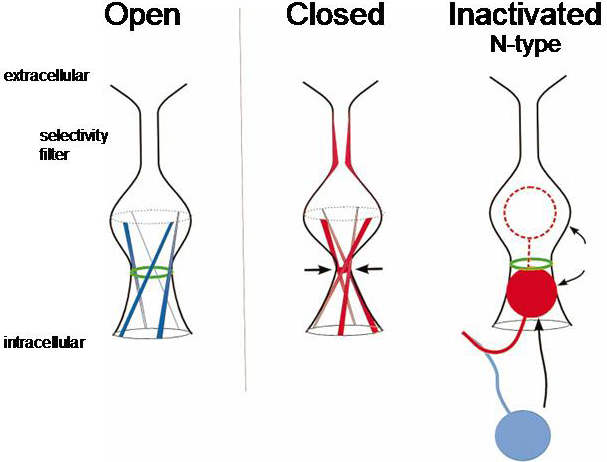
Figure 5 Cartoon showing the open, closed and inactivated states of the channel. Inactivation occurs when a region of the amino terminus known as the inactivation ball swings in to bind to the inner surface of the pore, physically blocking the channel and stopping ions from passing. Note that the closed and inactivated states are different, with different regions of the channel blocking or gating the pore.
The inactivation ball is located at the amino terminus of the protein. Using site-directed mutagenesis it is possible to delete the inactivation ball and show that this removes fast inactivation.
C-type inactivation is a more complex phenomenon, which involves constriction of the pore near the selectivity filter.